Published 16 October 202626 min
The Secret Chip That Made the ZX Spectrum Possible
How much of the ZX Spectrum was really inside one Ferranti ULA, and why could it stop the Z80?
The story runs from the ZX80's disappearing picture and Sinclair's component budget to a hand-drawn ULA and its reconstruction decades later, showing how it divided the Spectrum's work with the Z80.
Watch a loading screen reveal the memory map, colour jump across an 8 by 8 cell, and the processor's clock stretch beside the picture. Hear five apparent channels squeezed from one binary speaker output, then meet the speck of dust that rescued the only working sample on the first wafer.
Sources
Every fact in the film is tied to a quotation from a source. These are the 51 published ones, most cited first.
- 48K ZX Spectrum Technical Information (comp.sys.sinclair FAQ) (World of Spectrum)worldofspectrum.org · cited 37 times
- Contended memory (Wikipedia)en.wikipedia.org · cited 15 times
- Spectrum ROM Load Routine - World Of Spectrum Classicworldofspectrum.net · cited 14 times
- ZX Spectrum ULA (Sinclair Wiki)sinclair.wiki.zxnet.co.uk · cited 11 times
- Colour Clash: The Engineering Miracle of the Sinclair ZX Spectrum - Paleotronic Magazinepaleotronic.com · cited 11 times
- Memory contention and the Floating Bus (Spectrum for Everyone)spectrumforeveryone.com · cited 10 times
- L Break Into Program - ZX Spectrum Screen Memory Layout (L Break Into Program, 0:1)breakintoprogram.co.uk · cited 10 times
- Sinclair ZX Spectrum at 40: interviews with Crispin Sinclair, Richard Altwasser and Steven Vickers (RWTH Aachen University, Media Computing Group)hci.rwth-aachen.de · cited 9 times
- Sinclair ZX Specifications (Martin Korth (problemkaputt.de))problemkaputt.de · cited 8 times
- The ZX-Spectrum screen layout: Part II (Overtaken by events)overtakenbyevents.com · cited 7 times
- An Interview With ZX Spectrum Designer Richard Altwasser - Paleotronic Magazinepaleotronic.com · cited 7 times
- Contended memory (Sinclair Wiki)sinclair.wiki.zxnet.co.uk · cited 7 times
Show all 51 sources
- ZX Spectrum 16K/48K (Sinclair Wiki)sinclair.wiki.zxnet.co.uk · cited 7 times
- ZX Spectrum: screen memory layout (Whatnot and Gobbleaduke (blog))whatnotandgobbleaduke.blogspot.com · cited 6 times
- How the ZX80 works (Tynemouth Software)blog.tynemouthsoftware.co.uk · cited 6 times
- Attribute clash (Wikipedia)en.wikipedia.org · cited 5 times
- DIY Sinclair clones: Too late for Next? Just build your own (theregister)theregister.com · cited 5 times
- Planet Sinclair: Computers: ZX Spectrum: Spectrum 48K Versionsrk.nvg.ntnu.no · cited 5 times
- Chasing the raster on the ZX Spectrum in Sidewize (Steve Wetherill: Video Game Developer)blog.stevewetherill.com · cited 5 times
- The Sound of 1-bit: Technical constraint and musical creativity on the 48k Sinclair ZX Spectrum (G|A|M|E Games as Art, Media, Entertainment)gamejournal.it · cited 5 times
- Creating a ZX Spectrum Image Load Video (SteveTalksCode)stevetalkscode.co.uk · cited 4 times
- L Break Into Program - ZX Spectrum ULA (L Break Into Program, 0:1)breakintoprogram.co.uk · cited 4 times
- ZX Spectrum (Wikipedia)en.wikipedia.org · cited 4 times
- Floating bus (Sinclair Wiki)sinclair.wiki.zxnet.co.uk · cited 4 times
- Programming the ZX Spectrum’s Bitmap Display (Bumbershoot Software)bumbershootsoft.wordpress.com · cited 4 times
- Gate array (Wikipedia)en.wikipedia.org · cited 4 times
- Spectrum Clone Design Blogzxdesign.info · cited 4 times
- Spectrum Harlequin 128K - L Break Into Program, 0:1breakintoprogram.co.uk · cited 3 times
- ZX81 (Wikipedia)en.wikipedia.org · cited 3 times
- ZX Spectrum ULA Types (Spectrum for Everyone)spectrumforeveryone.com · cited 3 times
- Ferranti ULA (Petervis The Quantum Archive)petervis.com · cited 3 times
- Happy 30th Birthday, Sinclair ZX Spectrum (theregister)theregister.com · cited 3 times
- Graphics and Soundcrashonline.org.uk · cited 3 times
- Spectrum Clone Design Blogzxdesign.info · cited 3 times
- Clive Sinclair's 1982 Practical Computing interview (World of Spectrum)worldofspectrum.net · cited 2 times
- Spectrum Clone Design Blogzxdesign.info · cited 2 times
- Repairing A ZX Spectrum @ Retroleumblog.retroleum.co.uk · cited 2 times
- List of ZX Spectrum clones (Wikipedia)en.wikipedia.org · cited 2 times
- Sinclair User 88 - How The Hell ... Did the Technician Ted tape loader work?sinclairuser.com · cited once
- ZX80 (Wikipedia)en.wikipedia.org · cited once
- BBC Micro (Wikipedia)en.wikipedia.org · cited once
- World of Spectrum - Documentation - ZX Spectrum manualworldofspectrum.org · cited once
- Spectrum Clone Design Blogzxdesign.info · cited once
- L Break Into Program - ZX Spectrum Memory Map (L Break Into Program, 0:1)breakintoprogram.co.uk · cited once
- ZX Spectrum graphic modes (Wikipedia)en.wikipedia.org · cited once
- Sidewize (Wikipedia)en.wikipedia.org · cited once
- Spectrum tape interface (Sinclair Wiki)sinclair.wiki.zxnet.co.uk · cited once
- ZX Spectrum Issue 2 With ULA Modification - Computercomputinghistory.org.uk · cited once
- Spectrum Clone Design Blogzxdesign.info · cited once
- Spectrum Clone Design Blogzxdesign.info · cited once
- Writing a Demoscene Intro for the ZX Spectrum (markround.com)markround.com · cited once
Transcript
The narration as it is spoken in the film, chapter by chapter. Pick a time to play the film from there.
Read the full transcript
Those Loading Stripes Were Signals
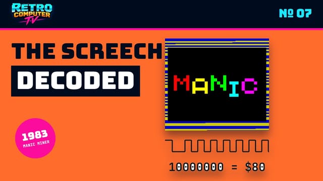
0:02These stripes are not a loading animation. The Spectrum is listening to pulses from a cassette, and its program changes the border colour every time it detects an edge. Then the picture appears in a peculiar order. The top third fills in strips, followed by the next two. Only at the end does the colour arrive. Every part of this familiar ritual leads back to one black chip.
0:37The Z80 ran the program. But the Ferranti ULA generated the picture, refreshed memory, read the tape and keyboard, carried the sound and border controls, and supplied the processor with its clock. When the two chips wanted the same memory, the ULA could even stop the Z80. So how much of the ZX Spectrum was really inside this one component, and why was it built that way?
When Thinking Erased the Picture
1:08To understand why the Spectrum needed the ULA, start with the ZX80. It had no video chip and no custom chip at all. Its Z80 processor spent most of its time drawing the television picture. Hardware tricked it into stepping through screen memory by executing no-operation instructions, one character position after another. That was wonderfully economical, but the processor could not draw and think at the same time. Press a key and the picture briefly disappeared while the machine dealt with it. Give it a substantial calculation and the screen remained blank until the work was finished.
1:58The ZX81 improved matters. Jim Westwood combined eighteen of the ZX80's separate logic chips into a Ferranti ULA. Its SLOW mode kept the display alive, but left the user's program with only about a quarter of the processor's time. For the next machine, colour graphics required a cleaner separation. Richard Altwasser, the Spectrum's hardware designer, later explained that moving from static to cheaper dynamic RAM created two more jobs: far more video data had to be read, and the memory itself had to be refreshed. The Z80 could not do all that while running the computer. Dedicated logic would have to do it beside the processor. And the solution had to be cheap. In 1982, the 16K Spectrum launched at one hundred and twenty-five pounds. The BBC Micro Model A cost two hundred and ninety-nine. Sinclair's arithmetic reached right down to the circuit board.
3:24Sinclair liked to compare this approach with grander computers. Looking at the IBM PC's colour circuitry in 1982, he said it occupied a board the size of a large coffee-table book, packed with perhaps a hundred chips. His conclusion was admirably short: “We do it on one chip.”
3:55That was salesmanship, not a literal circuit diagram. The Spectrum still needed its Z80, ROM, RAM and supporting memory logic. But the ULA was the device that made a low-cost collection of parts behave like a complete colour computer.
How the ULA Painted the Screen
4:18The division of labour was simple. The Z80 followed instructions. It ran BASIC, games and the routines in ROM. The ULA did not run a program and it was not a second processor. It was fixed electronic logic, doing several repetitive jobs at once.
4:46A 14 megahertz crystal supplied the master rhythm. The ULA divided that to make a 7 megahertz pixel clock, then divided it again to drive the Z80 and the peripherals at 3.5 megahertz. It also generated the frame interrupt that programs used to keep in step with the television picture. For the active picture, the Spectrum reserved 6,912 bytes of RAM. The first 6,144 held a monochrome bitmap, 256 pixels across by 192 down. Another 768 bytes held the colour information. That was one colour byte for each of the screen's 32 by 24 character cells.
5:46While the television beam crossed the picture, the ULA repeatedly fetched a bitmap byte and its colour byte. One said which of eight pixels were on. The other said what colours on and off should mean. Every four processor ticks, the next pair arrived. The ULA kept doing this line after line, frame after frame, whether the Z80 was ready or not. The bitmap's addresses were not laid out as 192 ordinary rows. They were divided into three interleaved sections. Within a character cell, moving down one pixel row was easy. Crossing into the next character row was less friendly. Technical accounts explain that the arrangement made the ULA's paired bitmap and colour reads easier for dynamic RAM, while also making the ROM's character printing compact. This odd arrangement became visible whenever a loading program wrote straight through screen memory. First came the top third, in interleaved strips. Then the middle and bottom. The colour bytes occupied the final section, so the finished drawing often remained black and white until its palette suddenly arrived. The loading screen was showing you the Spectrum's memory map.
Why Colour Came in Blocks
7:10The colour byte was an exceptionally dense bargain. Three bits selected the ink, the colour used for a set pixel. Three selected the paper behind it. Another bit made both colours bright. The last made them flash by periodically swapping ink and paper. There were sixteen possible dark and bright combinations, but bright black looked the same as ordinary black, leaving fifteen distinguishable colours. The catch was geography. One attribute byte covered an entire block of eight by eight pixels. Every pixel in that square had to share the same ink, paper and brightness. When a differently coloured moving character entered the block, something had to give. The character took on the background's colours, or the background took on the character's. This was colour clash.
8:17It was not an accidental smear from a weak video signal. It was the exact result of storing detailed light and dark pixels, but colour only once per character cell. Altwasser later said the design drew on three observations: human vision resolves brightness more finely than colour, PAL television gives colour less bandwidth than luminance, and Teletext had already made character-level colour familiar. Above all, 768 colour bytes were affordable.
9:15Programmers and artists turned the bargain into a style. The game recordings here are modern captures, probably made through emulation. Knight Lore kept each room essentially monochrome, so figures could move without dragging blocks of colour behind them.
9:39Lightforce designed its scenery, objects and movement around the eight-pixel grid. Full-colour action became possible because the artwork obeyed the boundaries that the hardware could not cross.
10:01Don Priestley went in the opposite direction and made Popeye enormous. He said the licence holders “demanded that Popeye had to look distinctly like his cartoon counterpart, complete with the right colour socks, hat and pipe.” The solution was a figure eleven characters high. At that scale, the colour grid became part of the drawing rather than an obstacle across it.
10:34Asked much later about the clash his architecture produced, Altwasser said, “Given the same circumstances I would be happy to take the same design decisions again.” It is difficult to argue that the compromise lacked character.
Drawn by Hand, Saved by Dust
10:54ULA meant Uncommitted Logic Array. Ferranti could manufacture a base wafer filled with a regular array of transistors before knowing what a customer wanted. Customer-specific metal connections were then added to turn those transistors into gates and complete circuits. It was quicker and cheaper to commission than a wholly custom chip, but unlike a modern FPGA, it could not be reprogrammed after manufacture. The bare die shown here is a later ULA from the same Ferranti family, not the Spectrum's own part. Its repeating cells show the idea: a field of available logic, given a particular purpose by the connections laid over it.
12:26Then the first wafer came back. A Ferranti engineer had missed one connection in a counter circuit. Almost every chip failed. One did not.
13:11A custom logic chip, designed by hand, temporarily rescued by dirt. The surviving sample let Altwasser continue testing, and the ULA went on to become the busiest component in millions of Spectrums.
The Chip That Stopped the Z80
13:31Generating the picture created a problem. The ULA and the Z80 both needed the lowest 16K of RAM. The processor might be fetching an instruction or changing the screen just as the ULA needed the next video byte. That memory could not serve both at once, and the television picture could not pause halfway across a line. So the ULA received priority. It did not use the Z80's formal bus request system. It simply stretched the high part of the clock signal that it was already supplying to the processor. From the Z80's point of view, time stopped. Once the video fetch was complete, the clock continued and the processor carried on from exactly where it had been frozen. Our two emulated captures run the same border-stripe program. On the left, it sits in the lower shared memory. On the right, it sits in the upper memory that the ULA never uses. The upper-memory stripes remain even. The shared-memory stripes stretch beside the active picture, because that is where the ULA is fetching data and holding the Z80.
14:54The delay followed a repeating pattern of six, five, four, three, two, one, zero and zero clock periods. It occurred only while the active 256-pixel picture was being drawn. In the border and retrace periods, the ULA did not need video memory, so there was no delay. Code and data in upper RAM could also run at full speed. This was memory contention, and programmers had to feel it in their timing. A sound routine placed in shared memory could become uneven. A carefully timed graphic effect could move. Even the Spectrum's nominal 50 hertz frame rhythm was really about 50.08 hertz, enough for a clock program to gain roughly six seconds in an hour. The same cost-conscious design produced a stranger gift. Rather than use proper bus-driver chips, the original Spectrum separated the Z80 and ULA data buses with 470-ohm resistors. If the Z80 read an unattached port while the ULA was fetching the picture, some of that video data could leak through. This became known as the floating bus.
16:21Sidewize programmer Steve Wetherill found by experiment that port 0x40FF returned colour attributes reliably. He hid one row of bright black attributes just below the play area. Bright black looked exactly like ordinary black, but its byte value was distinctive. The game waited until that value leaked through, revealing where the television beam had reached, then began drawing safely behind it.
17:00Wetherill called the technique “pretty empirical,” and admitted it failed on later hardware revisions. But for the original machine, a cost-saving resistor had become a timing sensor that was never intentionally designed.
Stripes, Beeps and Ghost Keys
17:19The ULA presented most of the Spectrum's everyday inputs and outputs through one conventional address, port 0xFE. Write to it and the bottom three bits choose the border colour. Another bit controls the cassette output. One more drives the internal speaker. Read from the same port and five bits report the keyboard, while another carries the cassette input. This is why loading looked the way it did. The ULA did not invent the stripes by itself. The Z80 was running the loader in ROM. The incoming tape signal reached it through the ULA. As the routine detected each new edge, it wrote a new colour back through the ULA-controlled border.
18:18While waiting for the leader tone, the ROM used red and cyan. Once it reached the actual bytes, it switched to blue and yellow. The two pulse lengths used for zero and one bits produced stripes of different widths. They were not a decorative progress display. They were the tape's changing electrical signal, translated into colour by software and the ULA. Sound used the same port and almost no hardware. The speaker was connected to a single ULA pin. It could be fully driven or at rest, with no intermediate volume. To make a tone, the processor repeatedly changed that one bit. Change it quickly for a high note, more slowly for a low one.
19:17Programmers pushed much further. By 1986, Tim Follin's Agent X routine was producing five apparent channels, with percussion, envelopes, portamento and phasing, all through that one binary output. Follin later said, “I think I'd pushed the processor too far actually!”
19:52The keyboard was another exercise in doing more with less. Its 40 keys formed eight half-rows of five. The Z80's upper address lines selected a half-row, and the ULA returned five key states. No controller chip was needed for each key. The printed membrane beneath the rubber keyboard completed a simple matrix.
20:26Matrices can also report keys that nobody pressed. Hold CAPS SHIFT, B and V together and the Spectrum can also read Space. Since CAPS SHIFT and Space mean BREAK, three real keypresses could produce an imaginary fourth and a “Break into Program” report. The speaker, EAR socket and MIC socket were even connected to the same physical ULA pin. On this computer, sound, tape, keyboard and border did not merely live near one another. They met at one inexpensive gateway.
Bugs With Legs
21:08Packing so much logic into one chip also packed in its mistakes. Some early Issue 1 boards needed an extra 74-series logic chip to correct a ULA timing error. It sat on a tiny board above the motherboard, supported on little legs. Engineers and collectors know it as the dead cockroach. There was also the snow effect. Under an unusual interrupt setup, the ULA could become confused while handling dynamic memory. It would miss a screen byte and reuse the previous one, filling the picture with apparent snow. The computer itself kept running. Altwasser did not remember the artefact being discussed during launch testing, and later said he might then have blamed lazy software rather than a possible hardware bug. Heat made the machine still more individual. The ULA was the hottest-running chip, and its timing could drift by one processor tick as it warmed. Later Ferranti 6C versions reduced power consumption and temperature, while board revisions tidied up other timing and memory problems.
22:28A repair guide still puts the ULA high on the list when a Spectrum begins crashing after it has been running for a while. One chip had removed a great many possible faults from the board, but when that chip failed, a replacement was not something an ordinary logic drawer could provide.
Rebuilding the Missing Chip
22:50Decades later, Chris Smith reverse-engineered the ULA and rebuilt its functions from ordinary logic chips. The large wired construction looked like the circuit board the Spectrum had avoided in the first place, but it made the hidden design visible and documented its timing closely enough to create the Harlequin, a compatible Spectrum clone without the original custom chip.
23:28The original manufacturing process is obsolete, and copying the ULA proved awkward because Sinclair used parts of the array for analogue work as well as digital logic. Modern replacements and FPGA recreations therefore have to reproduce more than a 3.5 megahertz Z80 and a block of RAM. They need the screen timing, contention, floating bus, port behaviour and even awkward differences between chip revisions, because real software learned to depend on them.
24:19Now the loading ritual can be read. The Z80 is measuring cassette pulses received through the ULA. Its ROM routine changes the ULA's border colour at every edge. Bytes enter the interleaved bitmap in memory order, so the picture grows in strips. The colour attributes come last. Meanwhile, the ULA is reading that same RAM to make the television picture, and it can hold the Z80's clock whenever their memory accesses collide. The secret was not that the ULA replaced the processor. It made an unusually effective division of labour possible. The Z80 ran the instructions people wrote. The ULA kept the machine's clocks, memory, picture and modest collection of inputs and outputs moving around it. The Spectrum's colour clash, loading stripes, thin beeper, keyboard quirks and exact rhythm were not separate eccentricities. They were the visible character of that partnership.
25:23For more stories about the hardware hiding inside familiar machines, subscribe to Retro Computer TV. If this changed the way you see the Spectrum, you can like the film too.
Credits
Every image, clip and piece of music in the film, with its licence and where it came from: the film's credits.
More on ZX Spectrum